3D Computer Vision & Robotics
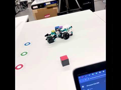
Calibrating the robot's environment using camera calibration with DLT, followed by cube picking and transporting it to a designated location
📷 1. Camera Calibration (DLT)
To convert 2D image coordinates into 3D world coordinates, the camera was calibrated using the Direct Linear Transform (DLT). A known set of 3D-2D correspondences was used to estimate the projection matrix P, allowing us to reconstruct 3D coordinates from a single image.
🔧 Key Steps
- Capture known 3D object points and their 2D image projections.
- Solve for the 3x4 projection matrix
Pusing least squares. - Use
Pto map future 2D detections into 3D world space.
📍 2. Localization of Robot and Objects
Using the camera's projection matrix, we estimate the 3D positions of all important elements:
- Robot base and arm
- Colored cubes (
r_cube,g_cube,b_cube) - Target locations (
*_target)
🔲 2D View of Localized Points (Z Flattened)


🧭 3D Spatial Layout
The following 3D plot visualizes the spatial relationship between robot components and objects:
📐 3. Distance and Angle Computation
Once all objects are localized, we compute:
- Euclidean Distance from the robot's arm to each cube.
- Orientation Angle required for the arm to align with the cube's position.
Demo Video
Click the image below to watch the result: